In this guide, I show you how to install a filament runout sensor on your Ender 3, Ender 5 and other Creality printers.
Hello, my name is Daniel, welcome to the CrossLink channel. I would like to help you being more successful with 3d printing and if you're here for the first time, subscribe and hit the bell notification icon so you don't miss anything.
So, I've got all these almost used up filament spools and believe it or not until today, I didn't feel the urge to have a filament sensor yet on any of my printers. Every time I saw that a spool was almost used up, I bought a new one.
But now it's time, I wanna use up all these rests to print some masterspools because I am trying to use the masterspool system as much as possible for the future.
So let's get this done.
What filament sensor do you need?
There is so many of them, different shapes, sizes. Mechanical, optical.
What should you choose?
I would say, choose the simple approach, use a microswitch with a roller at the end of the trigger arm. Either an old endstop switch or get it for a dollar from amazon and find a printable case that fits your printer.
But no matter if you buy or print a sensor and if it's mechanical or optical, a very important part will be to decide where to mount it?
I would say any place in the path of the filament that it has to go anyways is good.
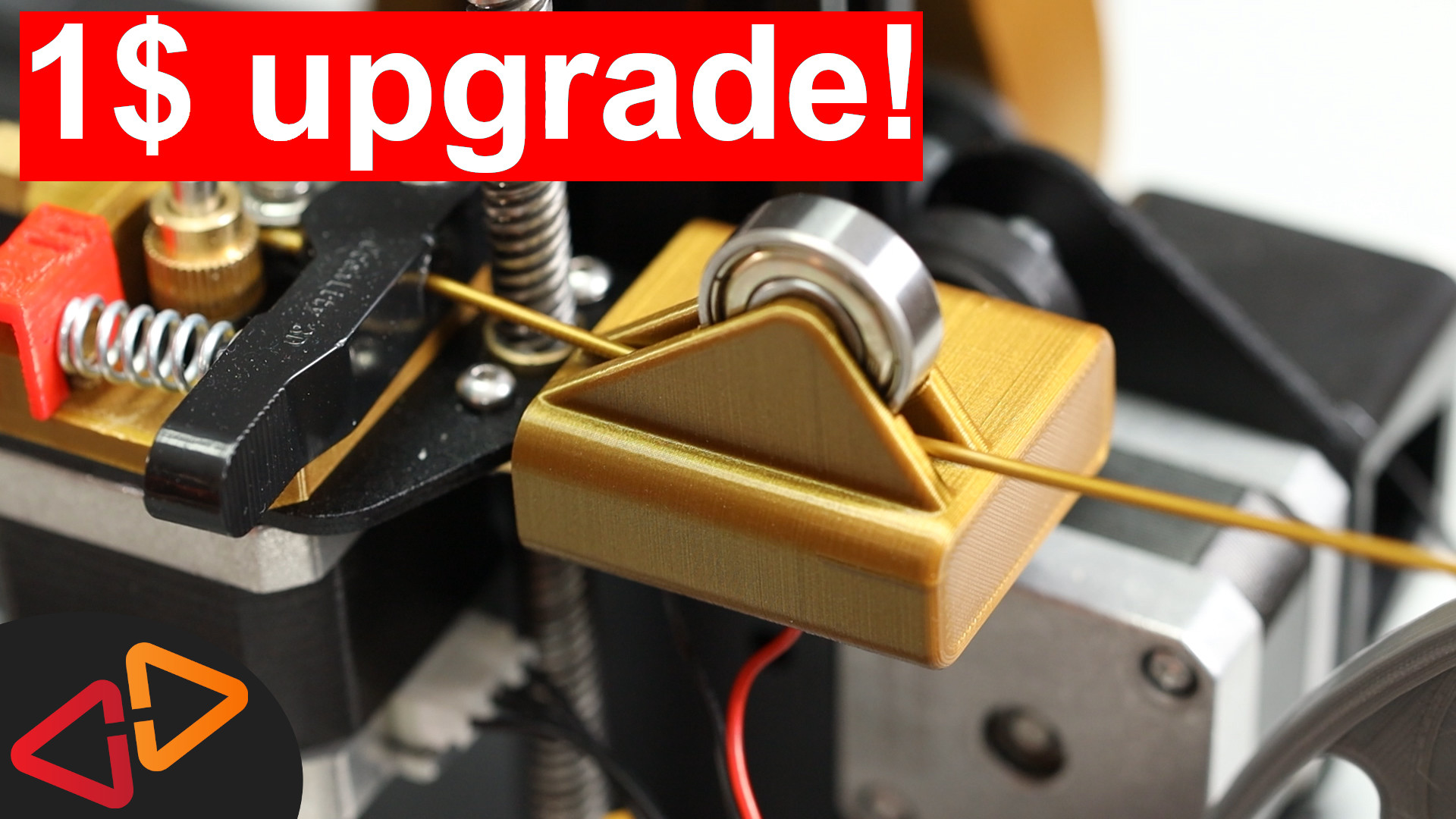
I have found a very nice solution on Thingiverse that I'm going to show you here - link is in the description.
This filament sensor requires no screws to mount it, it just slides into place next to the extruder.
And the best is - it works with spools mounted to the side as I have it here and also with the original position on the top of the printer just as good.
It has a 608 bearing that acts as a counterpiece to the roller on the microswitch so there is less friction on the filament running through the sensor.
The trigger switch also just gets inserted here and then it's locked in place with a printed locking piece that just slides into place - very elegant.
The bearing also acts as a strain relief for the extruder inlet itself and the filament that is routed from the top of the printer down to the extruder is less likely to break.
So the mechanics are clear, what about the electronics connection?
The switch I'm using for the filament sensor has three connectors. I will use the two outer connectors to connect them to the mainboard.
For that, I am soldering a two wire cable to the connectors.
Then, I lock the switch into it's place in the filament sensor and slide it into it's place next to the extruder.
Look how smooth and without any resistence the filament can be pushed through this sensor and then straight into the extruder.
I will cut the cable to a length of about 60 cm to route it in parallel to the extruder motor cable straight into the electronics case. Also I am adding dupont connectors to make the connection as clean and easy to do as possible.
As a prerequisite to using a filament sensor on the Creality stock mainboard, you will have to have a place to connect it to, that would be called a GPIO pin for the sensor where the trigger switch signal can be connected to the electronics of the mainboard.
So you should know that the Creality 8 bit mainboards that have been used up to today in most of Creality's cheaper models like the Ender 3, Ender 5 and CR10 and many other modesl don't have any additional connectors for things like filament sensors or a BLTouch probe by default.
Maybe that's going to change with new models that will have a 32 bit mainboard but we'll have to see.
But there is a solution for this. If you've missed my video about how to get TWO free GPIO pins on these Creality mainboards, I highly recommend to watch my video about it, I've linked it up here.
After watching that video, you will know how to either solder a cable to the mainboard to get PIN29 or how to install this cheap PIN27 display cable adapter to get a free PIN to connect your filament sensor. I've linked that adapter down in the description as well.
In case of the PIN27 adapter, you will have one of the sensor cables connected to PIN27 and the ground pin on the adapter
or in case you're using PIN29 you will find a free ground pin at the ICSP programming port.
That would be the lower right pin if you look at the mainboard with the SD Card reader facing to the right.
In this example I am using PIN27.
Another change I needed to make was to remix this case cover that I recommended in another video. The 60mm fan conflicted with the PIN27 adapter, so I moved the fan further back and now it fits again perfectly.
I've linked this new version also in the description.
Let's head on with the Firmware configuration.
By default, the filament sensor will NOT be detected by the onboard firmware be it the stock firmware from Creality or Marlin firmware as is currently on this printer, so we need to flash a new build of Marlin firmware to this mainboard anyways.
BUT - the last release build 2.0.5.3 by the time this video was made, has some bugs that prevented me from using it with the filament sensor so I had to go and use the bugfix-2.0.x branch.
And as a matter of fact, the current bugfix branch and probably any future release version will not build on a Windows computer.
I've talked about this problem in another video recently, so I'm not going into any details. Just be prepared that building the Marlin bugfix branch on a Windows computer will probably fail. I am going to post a few more videos on how to work around this issue very soon.
So make sure that you have the following things in place.
Have your computer ready to compile Marlin firmware with VSCode and Auto Build Marlin.
Have your Marlin 2.0 sourcecodes from the bugfix 2.0 branch ready and pre-configured for your printer so you just have to make the changes to enable the filament sensor.
I've made several other videos about how to configure Marlin 2.0 in general for these kind of printers, so check them out on my channel, if you need to.
So let's start to make the necessary changes.
Beginning in Configuration.h
go to about line 1173 to enable FILAMENT RUNOUT SENSOR.
And then you read here, for the filament runout sensor you need to define a value that's called FIL_RUNOUT_PIN
So let's add that here as #define FIL_RUNOUT_PIN 27 or 29, that number depends on your setup.
I have my sensor connected to pin 27 but in one of the next videos I will also add a BLTouch to this printer, so I'll probably gonna change this filament sensor to pin 29 as soon as I connect the BLTouch to pin 27.
Then, we need to open a file that's inside the src > pins > sanguino folder, that's called pins MELZI CREALITY.h
In this file, in the beginning, comment out the line stating #undef FIL_RUNOUT_PIN. Don't ask me why that is here, probably because of the fact that the beeper originally uses pin 27 but this line will prevent you from building the firmware if you don't comment it out.
Also if you are using PIN27 for the filament sensor you need to add another line here
#undef BEEPER_PIN
That's because the beeper on the stock mainboard also uses PIN 27 and the PIN 27 adapter interrupts this connection. However Marlin still believes it has a beeper and will try to use it until you add this line, so don't forget that in case you're using PIN 27.
Ok, back to Configuration.h because we're not completely done yet.
There is a few switches here that might be interesting for troubleshooting the filament sensor later.
One in particular is the FIL_RUNOUT_INVERTING switch. Currently it is set to false and we will double check if the sensor is working correctly with this value, reporting the right state when filament is in and out.
If this would not be the case, we could set this to true to invert the logic of the sensor input.
And then finally, the FILAMENT_RUNOUT_SCRIPT - here you define what command is executed once a filament runout event is detected. By default there is M600 and I am going to leave that as it is. This is why you need to enable the filament change feature in the first place.
Now, before you go and upload a new firmware version to the printer, make sure you note down all the settings you might have made that are saved to the EEPROM. That might be the filament load length settings for the M600 command or if you happen to have a z-probe installed, also note down your Z-offset values.
This is important because after the firmware has been flashed, the EEPROM might need a reset and all your previous settings that you made and saved through the printer menu might get lost.
Ok, so let's save all changes and upload the firmware to the printer.
As I said, If you get an EEPROM error, please also confirm to reset the EEPROM.
The first thing, I'd like to test is the sensor states if they report correctly to the firmware. To test this, I'm again using Pronterface, so let's connect it to the printer.
The command we need to use is M119. It reports back the state of the endstop switches and the filament sensor.
When the filament is out, M119 should report filament open.
And when the filament is inserted, M119 should report filament TRIGGERED.
If that is just the other way around in your case, you need to go back to edit your Marlin Configuration file and set FIL_RUNOUT_INVERTING to true and upload a new firmware build to your printer.
So, after making sure, the sensor reports the correct values, let's do a first test print to see the filament runout sensor in action.
Another thing to mention here, by the time this video was made, NOT having filament in the printer when you start a print doesn't trigger an initial filament change. So the printer will just start printing as if it has filament loaded. This is a known bug in Marlin 2.0 bugfix. It's probably going to be fixed in the near future but it's not working today.
So, let's start a print from the SD card.
Our print is running since a while, let's just cut the filament right here....
And as soon as the switch triggers, the printer moves into the parking position and starts the filament change.
So, I am inserting the new filament now.
And I finally have to confirm at the printer that the new filament is coming out of the nozzle.
Then, the printer continues to print as expected. Awesome!
So that's how to install a filament sensor on your Creality printer and the stock mainboard.
Next up, we will install a BLTouch sensor on this Ender 3 and see how we can cram all these features into Marlin firmware on the stock mainboard, so stay tuned for that video.
I've also linked two other interesting videos here for you. See you next time, Bye bye!