NOTE: THIS GUIDE IS WORK IN PROGRESS! EXPECT FREQUENT CHANGES IN THE NEXT WEEKS (DECEMBER 2023/JANUARY 2024)
Introduction
This guide is supposed to help you building your first THE100 3D printer step by step from sourcing the right parts to printing the STLs of the printable parts to assembling the final printer and getting it up and running with Klipper.
This document is based on my own experiences building the printer (December 2023) and the original available video guide from Matt The Printing Nerd on YouTube (https://www.youtube.com/playlist?list=PLM01o_dfwbDcKYB-9yV0vLs5k0CrHUv0W).
It is meant to be a companion guide for those of you who don't only want to watch videos but who like to have a written step by step guide. I also find it easier to update a written guide vs. re-recording a whole series of videos if little things are inaccurate, could be explained better or might change over time but that I leave up to you to decide.
What I like to encourage you to do as soon as you realize that I made a mistake or something is not accurate anymore: Please let me know immediately through either adding a comment to this page or contacting me via X, formerly Twitter (@danielcrosslink) or Instagram (@danielcrosslink).
I'm also curious to hear about your own builds, so please do not hesitate to post your pictures or messages here to show your progress and ask any questions that you might have. I am really interested to see how others are doing and what struggles they run into to improve this guide with your feedback! Thank you again.
Sourcing the non-printed parts (BOM)
Choosing the right parts for your THE100 build is essential to get the best results. However I figured that following Matt's original BOM spreadsheet it's sometimes not possible to find all the parts at the low prices he mentioned in his list. It might be possible during Black Friday week or if there is a special discount but normally, I would expect to pay 10-20% more for the parts unless you do extensive research on alternative suppliers.
I sourced most of my parts from Aliexpress and I have create an updated BOM with my choices for you so you can follow along but you don't have to. One major difference (also from a pricing PoV) will be the choice of hot end and nozzle. I already had a Rapido UHF hot end in my arsenal to re-purpose for the build but that's 3x as expensive as the originally suggested CHC Pro hot end from Aliexpress, so keep that in mind.
Also the CHF nozzles from Aliexpress might be cheap but if you decide to go with the Bondtech originals, you pay 10x the price as for the cheap Aliexpress clones.
So there is always this trade off to either go with the expensive but original quality parts or to risk potentially (not necessarily) lower quality and go with the cheap clone versions. Same for the BMG "style" extruder, which can of course also be an original Bondtech but I went for the TriangleLabs BMG clone.
Here is my version of the BOM with my own affiliate links: https://docs.google.com/spreadsheets/d/1b2mwuB-C6b_91lZDys-AQxH35ZaICRCfcd6Kh12H7S4/edit?usp=sharing . If you use those links to purchase anything you're supporting me in keeping this guide up to date and you're not paying more. Thanks a lot!
DryLins vs. steel linear bearings
Linear bearings can be purchased in two different flavours: Plastic DryLin bearings and steel linear bearings. However, there is some differences I like to highlight between those, so you can make the best choice for your setup.
DryLin linear bearing's biggest advantages are lower weight and lower noise. They have usually also less play on the linear rods so could potentially generate better printing quality. But, they are also much harder to match to the 8mm rods so they really run smoothly.
In the first iteration of my build, I tried to go with DryLins on the X and Y axis but I could not find any solution to make them run smoothly, not creating a lot of initial friction. Because what you need to know is that DryLins might actually run nicely once they have started moving on the linear rod but getting them started moving needs a lot more initial force than I anticipated. That's why in the end, I went for using only steel linear bearings on all axis and completely abandoned the idea of using DryLins.
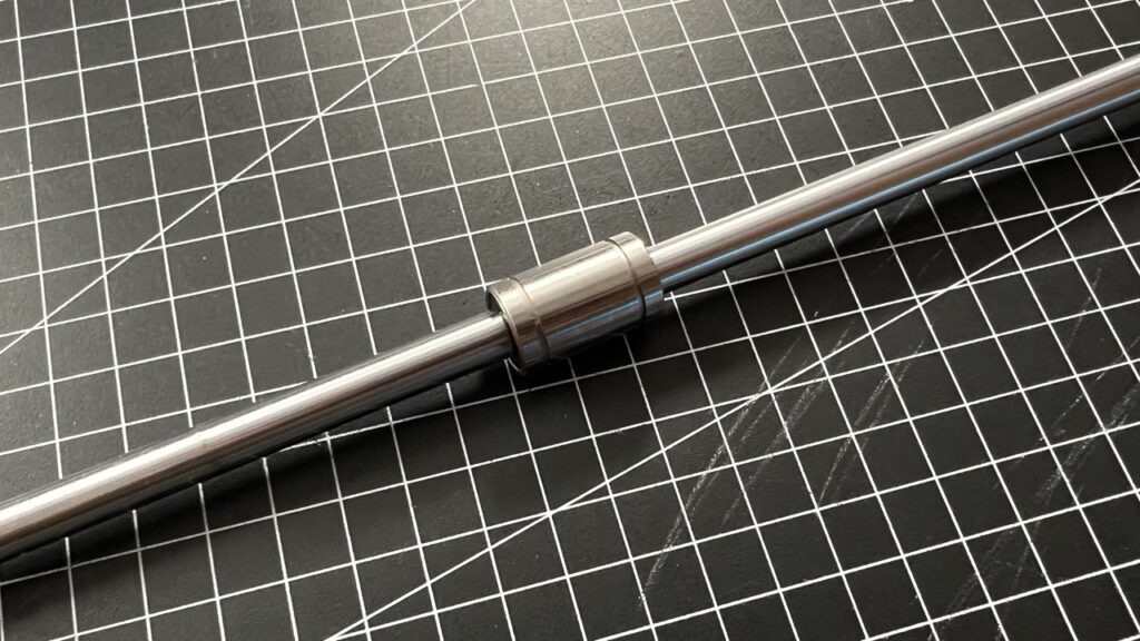
Steel linear bearings however are usually much louder and a bit heavier than DryLins. It's again a tradeoff and instead of using the cheap ones, you might want to consider buying the THE100 Linear Motion Kit from Aliexpress that Matt created in a partnership with Fushi: https://s.click.aliexpress.com/e/_DeZpVGH (then don't order the 8mm 250mm linear rods separately anymore)
Preparing the printed parts
Material choice
You can use PLA for any of the printed parts, however if you are thinking about enclosing the printer to print high temperature materials in the future or you plan to print for a long time with materials like PETG, which require higher bed- and nozzle temps even without an enclosure, I highly recommend to print your parts in ABS or ASA. Of course that will require to do this with another printer, which is already enclosed.
I decided to print my parts on the Bambu Lab X1 Carbon using ABSx from Nobufil (https://nobufil.com), which has a lower tendency to warp and smaller parts can even be printed without an enclosure, however for the bigger parts, I highly recommend using an enclosure with any type of high temp material.
Print settings
Regardless of the material choice, you should print all parts with at least 3 perimeters and 25% infill for stability. (Basically, you can just replicate Matt's print settings from the github page). Any more infill adds unnecessary weight with little gains in stability, anything lower might be too risky to break at higher speeds. Don't compromise on the number of perimeters either. 3 is really the minimum.
For layer height, you may use 0.2mm or 0.25mm, it will save you print time, however I went with 0.2mm for better visual quality but that's up to you. Matt used 0.
Print orientation
All parts are already oriented in the right way if you download them. Your slicer program should use that orientation. If you like to double check suggested orientation of any parts vs. what your slicer shows you, go to the GitHub project page (https://github.com/MSzturc/the100/tree/main/STL) and open the STL files there to see the original suggested part orientations in the preview mode.
Support material
Generally, I printed all parts with support on build plate only and normal support structures. I do not recommend using organic supports as the parts are very rectangular and normal supports just work perfectly for that.
The parts, where I had to set up the supports manually was for the fan duct. I limited the generation of supports for that part to only have them up until the point where the 5015 fans are inserted into the fan duct funnels. Any support above that would reach into the blower funnels and be very hard to remove.
Threaded inserts / Heat press inserts
This project contains a significant amount of heat press inserts that you need to melt into the printed frame parts. I personally prefer to do this with my DIY heat press insert workstation that is based on a Dremel vertical drill stand (Dremel 220 Workstation) and a 3D printed soldering iron holder (https://www.printables.com/model/405918)
Inserting the heat press inserts is also possible just with a soldering iron but it takes a bit of practice to get it right and especially to get the heat inserts really inserted vertical into parts and flush with the surface.
As Matt has shown in his build videos, you can push the heat insert into the target hole, while it's still cold. Then you touch the surface of the heat insert with the fully heated up soldering iron and wait until the plastic starts melting and the heat insert starts sinking in. Finally you make it flush with the surface by pressing the whole part agains a hard surface, ideally flat and non-inflamable like stiff cardboard, a flat block of wood or a wooden workbench table.
In the end it's up to you if you like to invest in a heat press workstation and modifying your soldering iron with heat press tips like the ones listed here: https://geni.us/heatinserttips
Required tools
- Soldering iron
- Threaded insert adapter for your soldering iron
- Wire cutter
- Allen keys/Hex-wrenches or Hex-drivers
- X-mm
- ...
- ...
Assembly guide
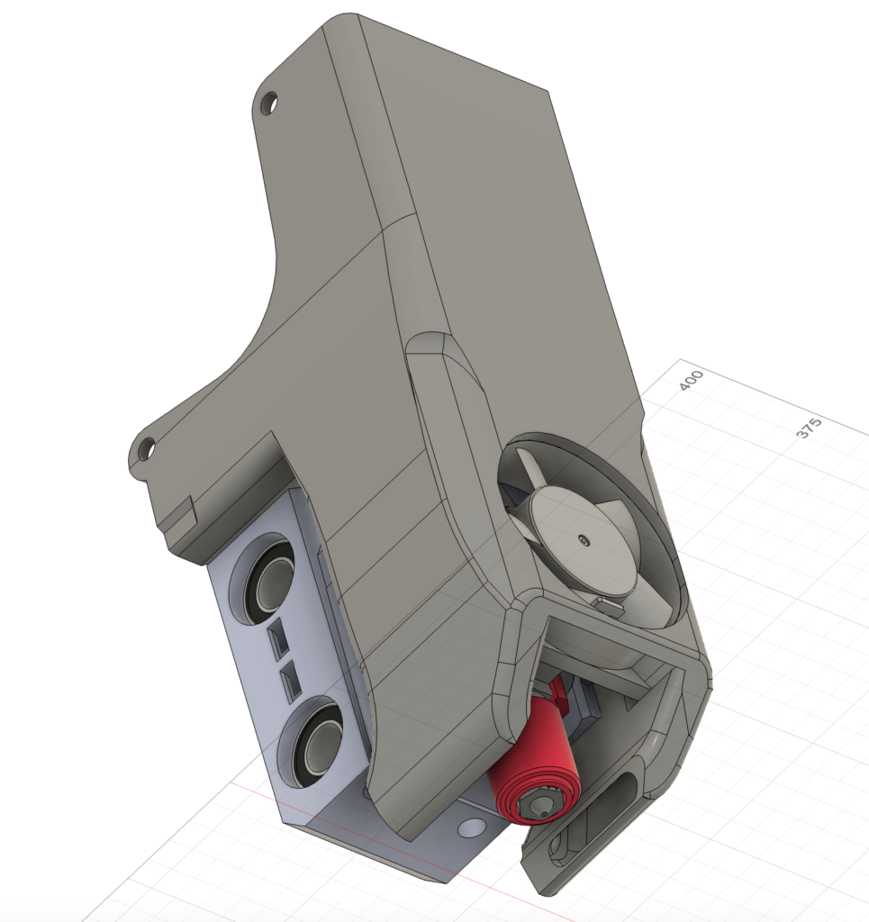
Tool head


| Difficulty: Easy |
| Steps: 10 |
| Get entire manual as PDF: |
Tools necessary for this chapter
Wire cutter
Soldering iron
2.5mm Hex-Driver / Allen-Key
Optional: Heat press insert tool for your soldering iron and/or heat press insert workstation
Tool Head required hardware
CHC hot end or Phaetus Rapido UHF hot end
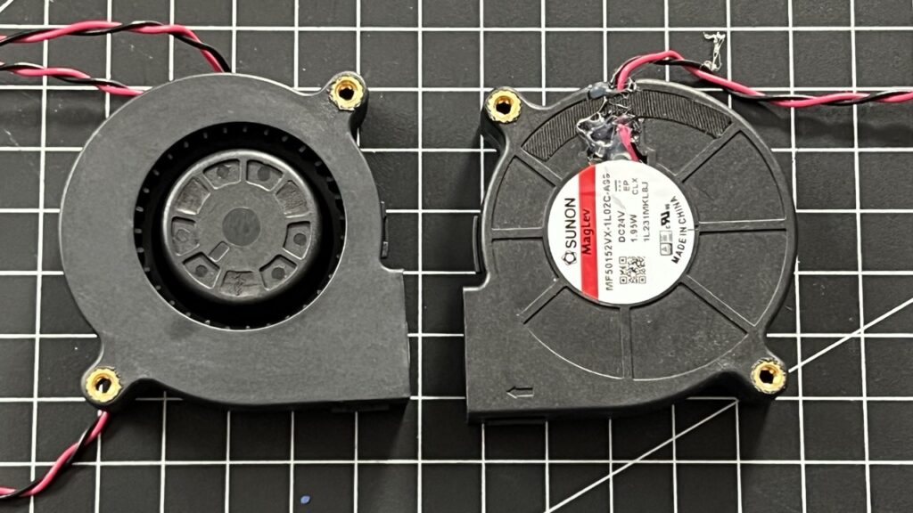
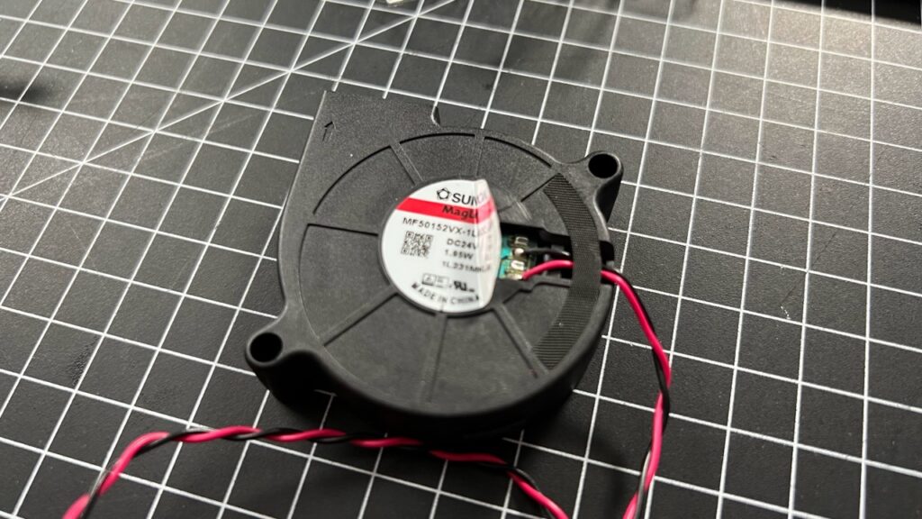
2x 5015 Turbine Blower Fan, 24V
1x 4010 Axial Fan, 24V
2x LM8UU linear bearings
11x M3 6mm screws
1x M3 35mm screw
4x M3 14mm screws
14x Heat press inserts
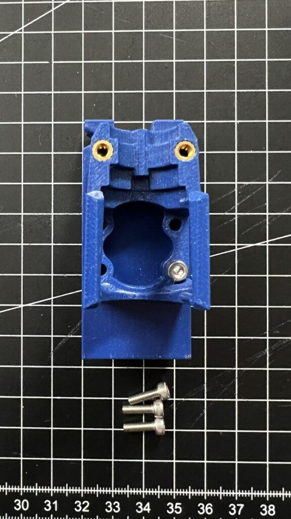
Tool Head printed parts
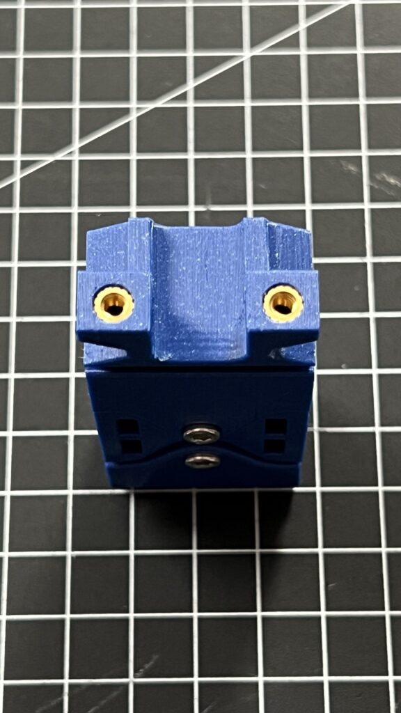
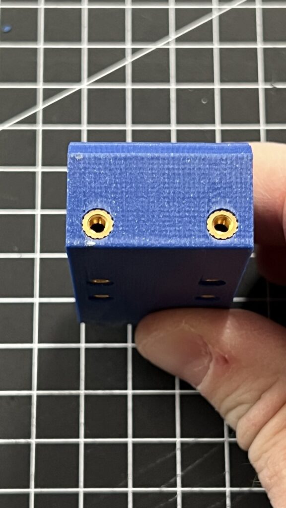
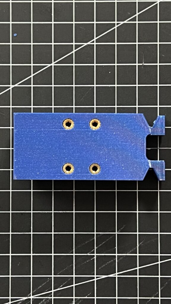
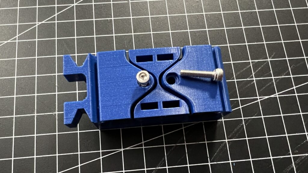
1x Adjustable Rod-Cradle (by Chazz Blackwell)
1x Connector Plate.stl
Depending on your hot end:
For CHC Pro
1x CHC Fanduct.stl
1x CHC Pro Clamp.stl
1x CHC Pro Mount.stl
4x M3 6mm screws?
For Pheatus Rapido UHF
1x Fan Duct.stl
1x Hotend Clamp.stl
1x Hotend Mount.stl
4x M3 10mm screws
Inserting the heat press inserts
Inserts 2 heat inserts into the front of the Hotend mount.
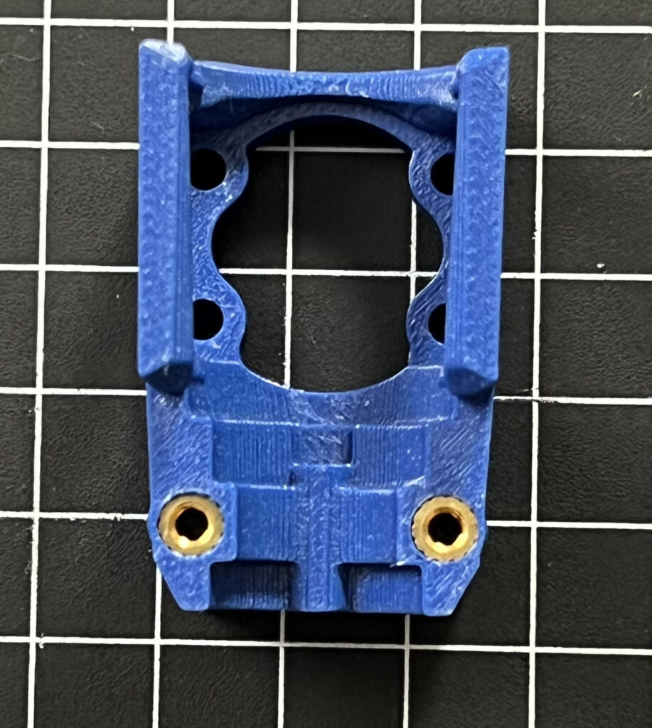
Mount 8 heat inserts into the "Rod-Cradle". Two go into the top, two into the bottom and four into the front. Use the method described in chapter "Heat press inserts".
The Fan duct requires 2 heat inserts into the back and two into the top.
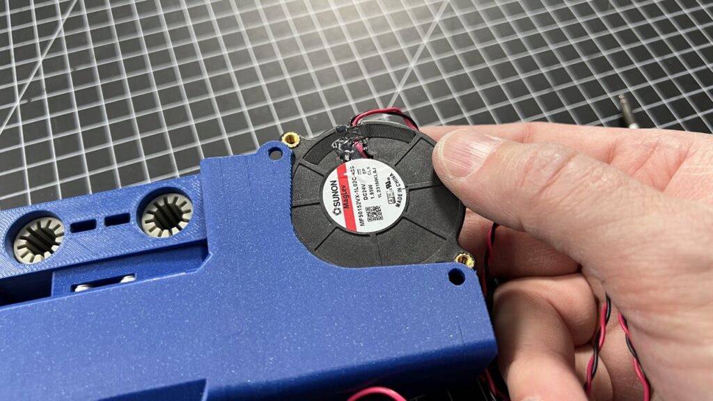
Insert 2 heat press inserts into each blower fan. To figure, from which side to to this for each fan, decide, which fan you will mount to which side of the fan duct. Then, insert the heat press inserts to the side of the fan, that faces outwards. Of course, don't do this while the fans are still in the fan duct.
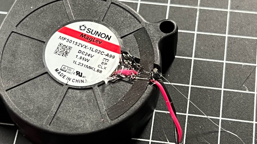
Securing the blower fan soldering points and wires
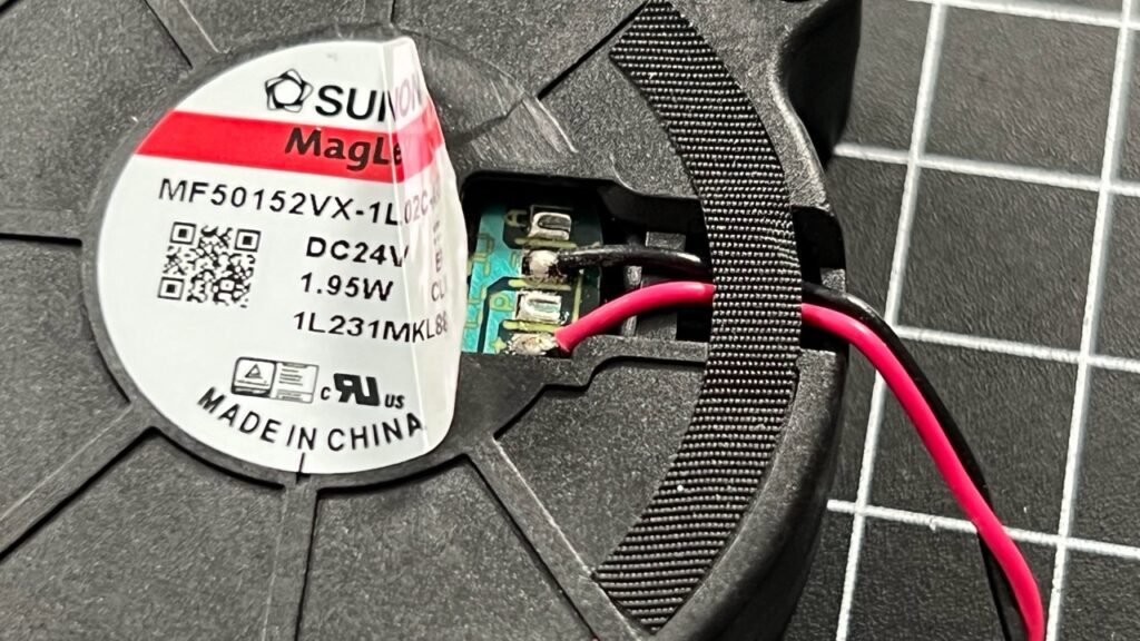
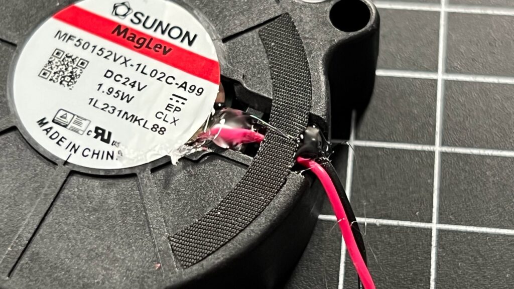
The blower fans come with pre-soldered wires. Due to the high printing speeds and possible vibrations and strain on the cables, please consider fixing the cables stronger to the fan PCB using either fluid glue or hot glue.
Remove the sticker from the side. Add glue on top of the solder points and also glue the cables into the holding bracket on the side so they cannot move anymore.
Testing the Linear bearings for the X-Axis
The Tool head runs on two linear rods using LM8UU linear bearings. However not all linear bearings are equally good even if you order them from the same source. You should test the bearings on the rods you intent to use for the X-Axis before you mount them into the Rod-Cradle.
Ideally, the bearings slide smoothly on the linear rod without any huge noticeable play. You should test this with a couple of bearings to find the best pair for the X-Axis.
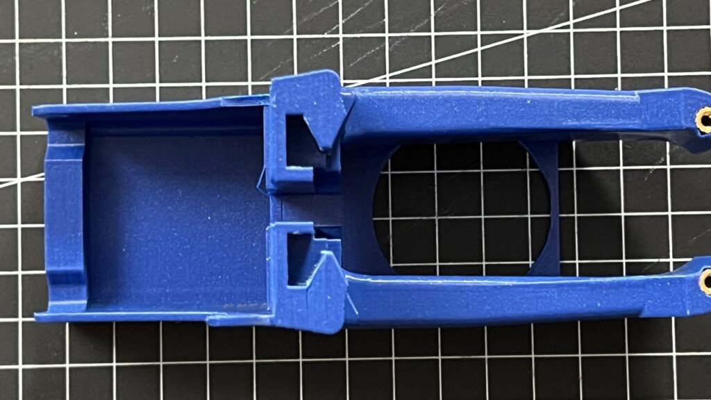
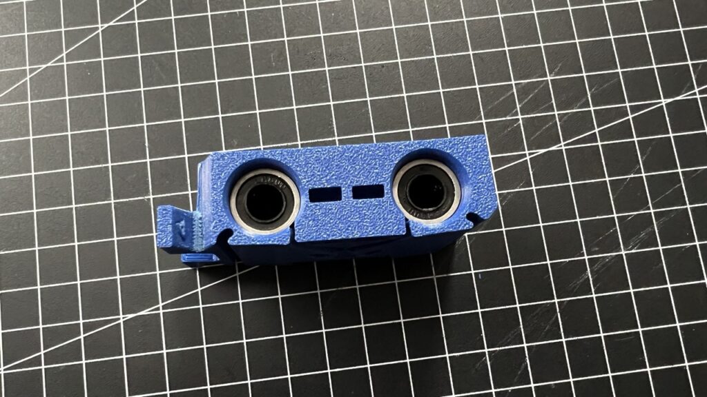
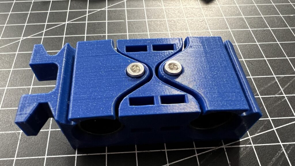
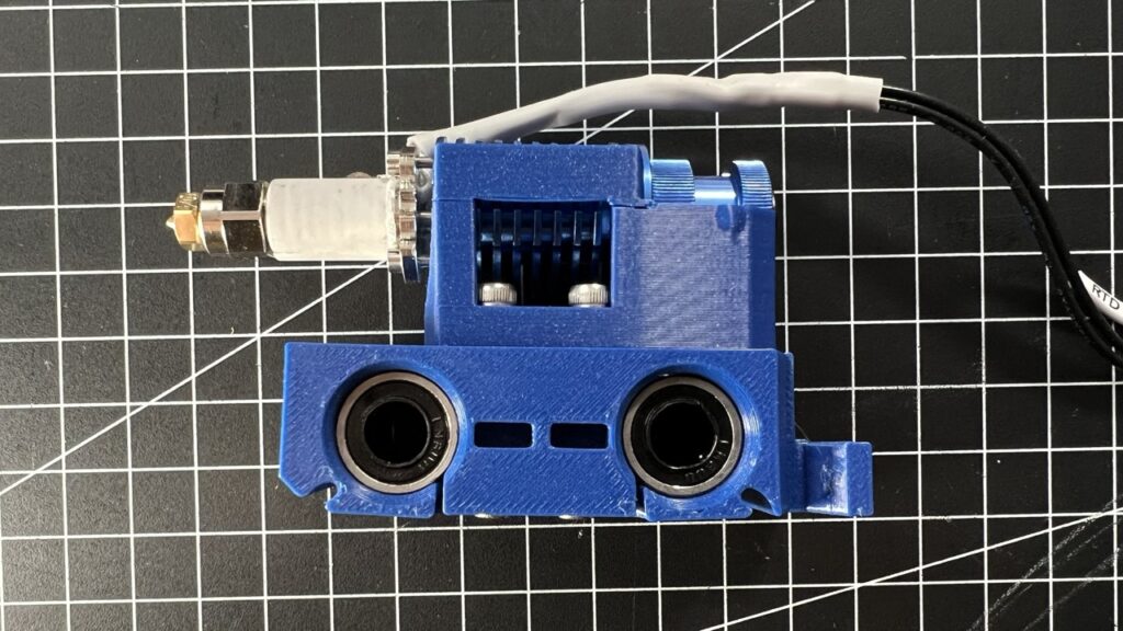
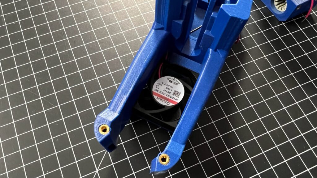
Fixing the linear bearings into the Rod-Cradle
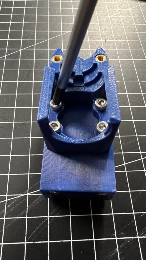
Now it's time to mount the linear bearings into the Rod-Cradle. Push one bearings into each hole so they sit in the middle of the slot. Then secure the bearings using two M3x14mm screws into the rod cradle.
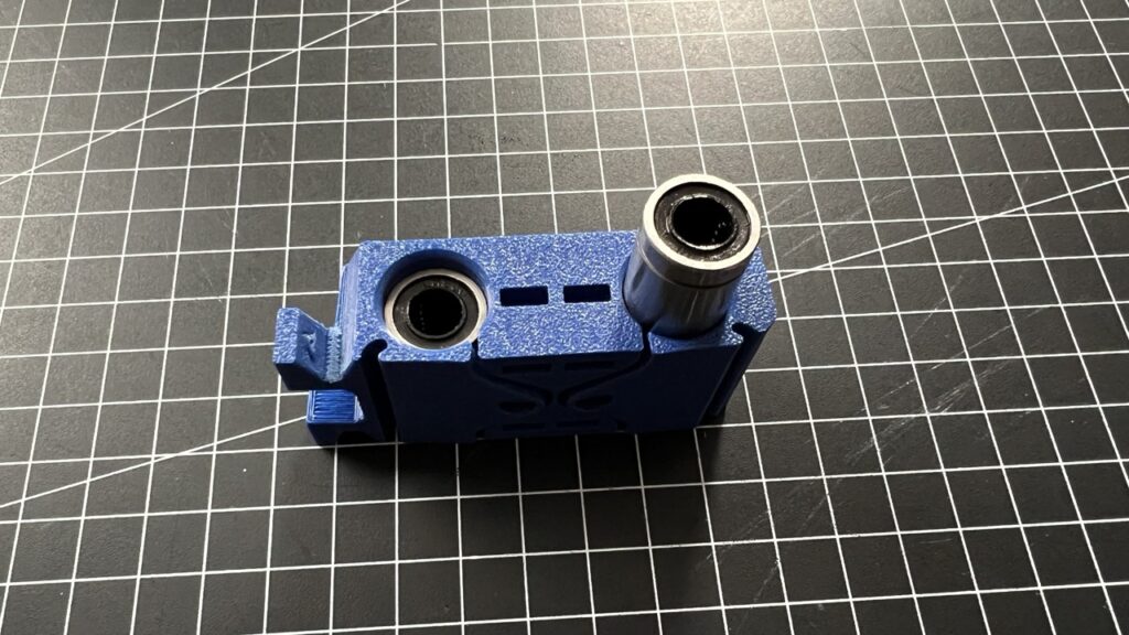
Attaching the Hotend-Mount to the Rod-Cradle
Take the hotend-mount (in my case for the Pheatus Rapido UHF) and align it's screw holes with the four heat press inserts of the Rod-Cradle.
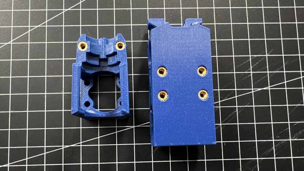
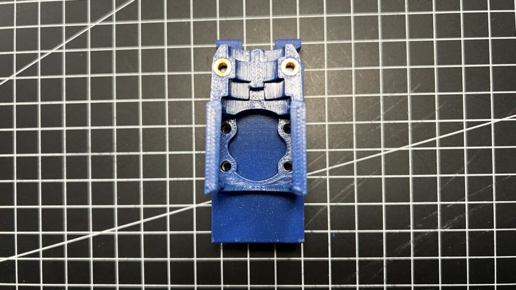
Fix the hotend-mount to the rod cradle using 4x M3x10mm screws. Using a ball-head hex-driver makes this much easier as the screws are not fully reachable straight from top.
Preparing the Hotend for mounting into the cradle
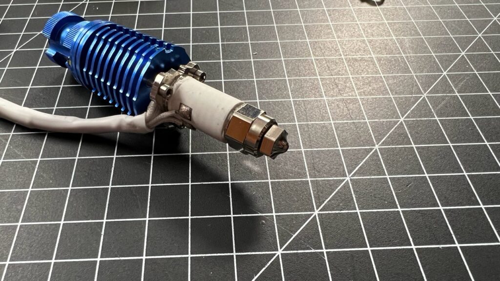
Depending on the hotend your're using you need to prepare it for finally mounting it into the cradle. Both the CHC-Pro and the Phaetus Rapido UHF have their cables coming from the heater and the sensor in a 90° angle from the hotend. They even have a metal bracket holding those cables straight sticking out from the hot-end.

These cables will have to run behind the hot-end inside of the fan duct, so we have to remove that holding bracket before we can continue.
In the case of the Rapido UFH, I first removed the small zip tie, that fixed the cable to the bracket and then I tried to cut off the bracket using a strong clipper. However the bracket was still to solid to do this.
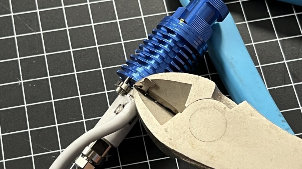
I then decided (thanks to the live-stream chat's suggestion) to disassemble the hot-end so I could reach the bracket's mounting screw, remove that and by that being able to remove the bracket without damaging anything.
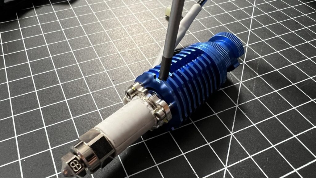
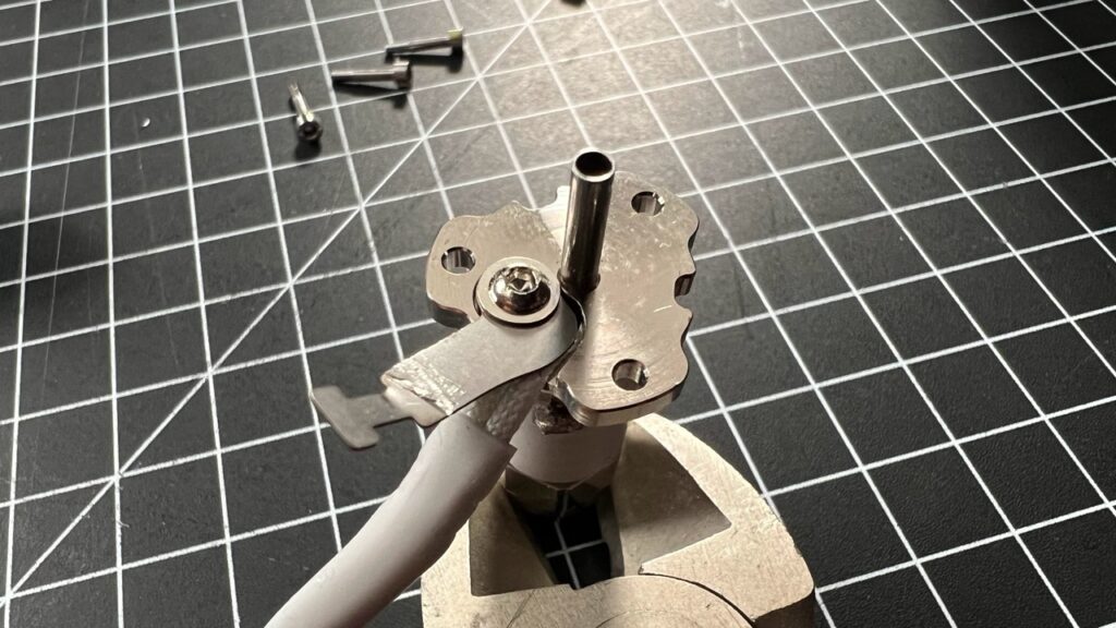
Then, reassembling and fixing the heater back into place was the last thing.
Now, I could bend the hotend cables upwards so they would be running alongside the hotend towards the upper end of the fan duct.
NOTE: Be careful with pulling the cable up, not to cause the soldering points to come loose.
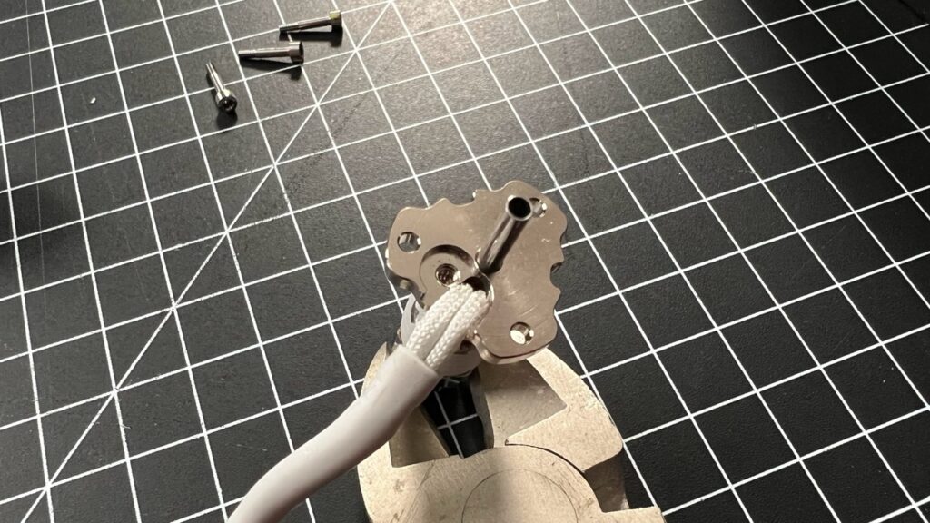
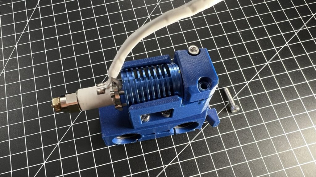
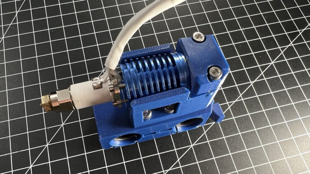
Fixing the hot end into the hot end mound on the rod cradle
The hot end is now inserted into the hot end mount on the rod cradle. Gently push the hot end into the cradle as shown in the image. The hot end has to sit flush in the mount so there is no significant gaps especially at the side where the heat press inserts are.
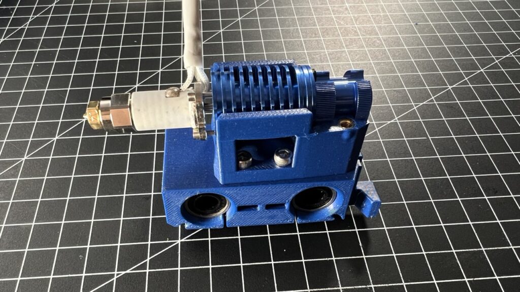
Make sure, the cables are facing away from the cradle as they have to run alongside the cooling fins to the upper end of the fan duct.
I broke one of the side wings while inserting my hot end into the mount. Instead of-reprinting, I re-attached it using CA glue. So no big deal if that happens, those wings do not have a huge effect of holding the hot end once it's fixed using the clamp in the next step.
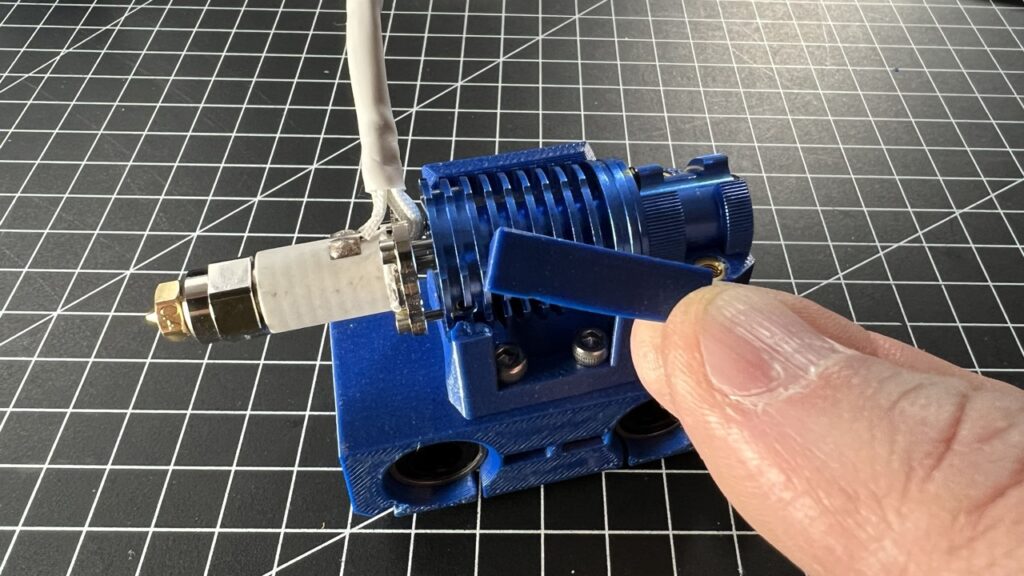
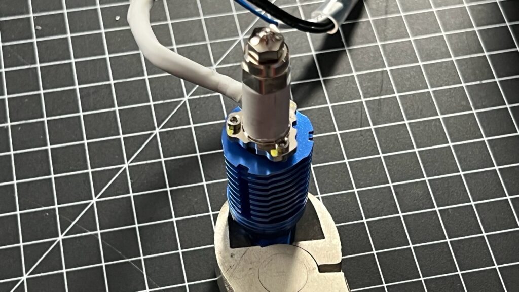
Attaching the hot end clamp
Finally, the hot end is fixed to the mount using the hot end clamp (Rapido UFH) with 2x M3x14mm screws (M3x12mm for the CHC Pro but please check yourself as I didn't have that hot end at hand)
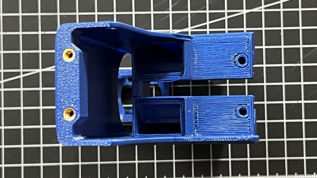
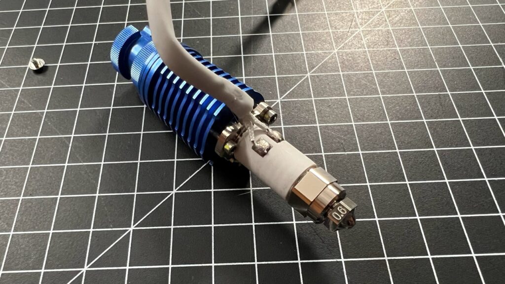
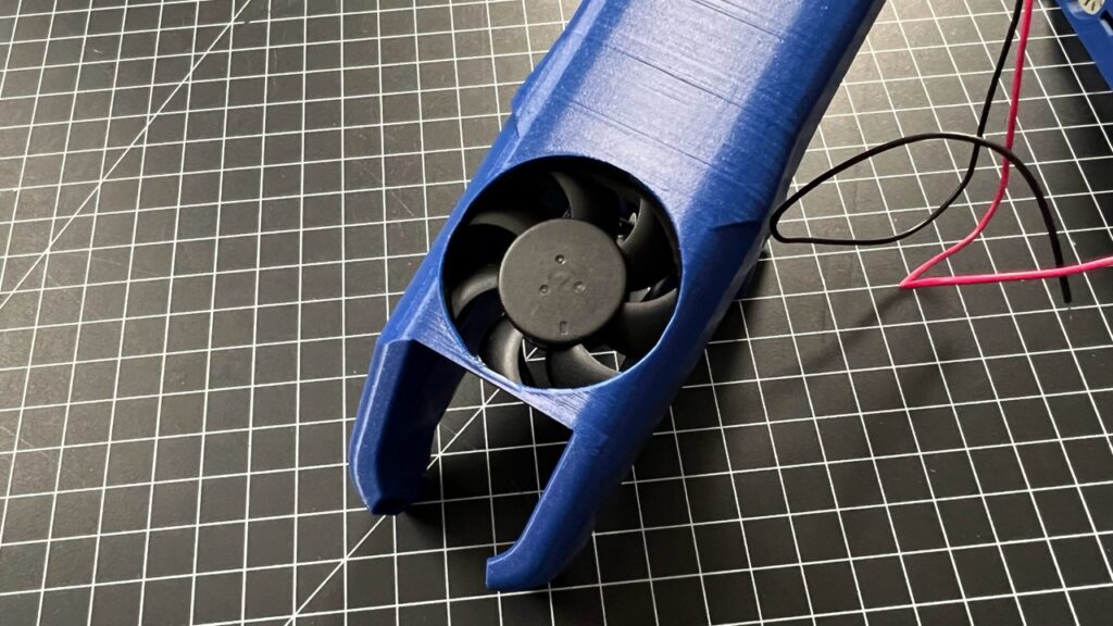
Inserting the 4010 cooling fan into the fan duct
Orient the 4010 fan so it's cable outlet is facing away from the upper end of the fan duct and the sticker is facing upwards so the fan would be blowing air towards you.
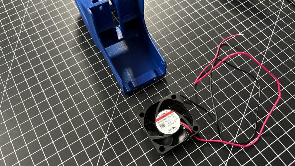
Insert the fan into the fan duct. You need to push the fan all the way forward into the slot in the fan duct even if there is quite some resistance - this is intended so the fan does not come out and needs no screws to mount.
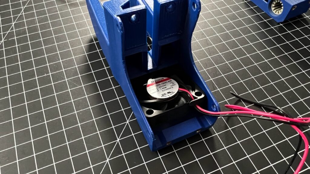
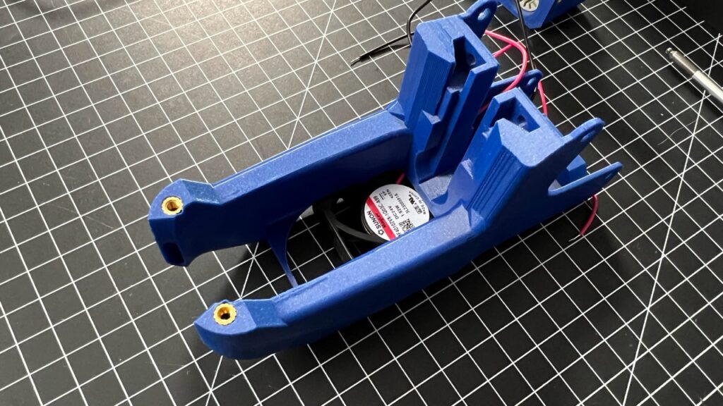
In the end, the fan duct should be inserted all the way into the slot, touching the very end of the slot. If you look at the fan duct from the hole side, you should see the unlabelled side of the fan, that's the correct orientation so the fan will blow air into the duct to cool the hot end.
Fitting the Rod cradle into the Fan duct
This is probably very dependent how well your 3D printer is calibrated and how much warping of parts you get printing the the100 parts. In my instance, I had some issues sliding the rod cradle into the designated slots, which hold everything in place. So I had to sand and file them a bit to make the two parts come together without any great forces required. You can force them together if you need to but getting them apart any time in the future might then become a huge problem, so I decided that I would make the fit as tight as possible while still being able to take both parts apart with little force.
Attach hot end assembly to fan duct
Start by gently pushing the heater and sensor cables of the hot end through the opening next to the 4010 fan. The CHC Pro fan duct has more space for the cables to come through but the Rapido UHF version has a much smaller gap.
Next, insert the rod cradle into the fan duct slots and if you've done the fitting nicely, it will slide in place without force. Push it all the way in, then secure both parts together with 2x M3x6mm screws.
Now, use the Connector Plate part and fix it to the rod cradle using 2x M3x6mm screws. Then fit the Connector Plate to the Rod cradle using 2x M3x6mm screws.
Mount the two 5015 blower fans to the fan duct
Start with the first fan and mount it with 2x M3x6mm screws to the fan duct. Make sure the Fan is sitting flush with the air inlets of the duct before you tighten the screws. Nothing should be under tension.
Then insert the second fan and use 1x M3x6mm screw to fix it to the fan duct using the hole close to the rod cradle.
Then use the long M6x35mm screw and use that in the second mounting hole. Screw it all the way in and hold the cables to the back of the fan duct so they are finally kept away from the gap between the blower fans by the 35mm screw.
Congratulations, you've assembled the tool head! Time for a final test sliding the two x-axis rods through the bearings.